Garmin Part Number: 010-00321-36
Last Updated: 05/25/2019
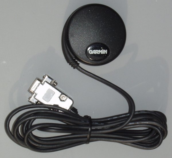
GPS 18x LVC Specifications:
- Integrated GPS Receiver and Antenna in One Small 61 mm (2.4 inch) Diameter Package
- 1 Pulse Per Second CMOS Output Accurate to 1 Microsecond Synchronized to GPS (UTC) Time
- 12 Parallel Channel GPS Receiver with WAAS
- < 15 Meters Position Accuracy without SA, < 3 Meters with WAAS
- Time to Fix: Cold - 45 Sec, Warm - 38 Sec, and Reacquisition - < 2 Seconds
- NMEA 0183 Version 2.0 and 3.0 Output Messages; GPALM, GPGGA, GPGLL, GPGSA, GPGSV, GPRMC, and GPVTG
- 4800 Baud Default Comm Port Speed
- WGS-84 Map Datum
- 1 Per Second Update Rate
- -185 dbW Receiver Sensitivity
- 0.45 Watts Power Requirements
- Input Voltage / Current - +4.0 to 5.5 DC at 90 MA
- -30° to +80° Centigrade or -22° to +176° Fahrenheit Operational Temperature
- >Weight - 116g
- 5 Meter (16 Feet) Cable Length
- USB Power Option
- More Specifications...
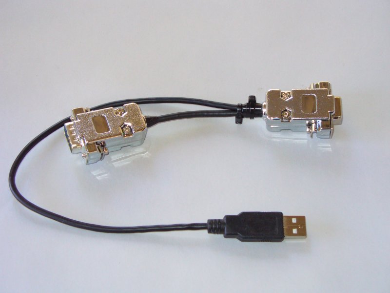
USB Power Y-Cable for Extension Cable
Price:
Garmin GPS 18x LVC: $90.00 each plus shipping. Price includes the female 9-Pin RS-232 connector soldered to the signal/power cable.
50 Foot (15.24m) RS-232 Extension Cable Option: $25.00
USB Power Option: $20.00 With this option I solder the USB power cable directly to the DB9 connector alone with the wires from the GPS receiver. This option can be used if the receiver will be near the computer. The Y-Cable option below can be used if you want to extend the cable between the computer and the receiver and have the computer supply the power to the receiver.USB Y-Cable Option: $35.00 This option allows the user to power the receiver at the end of an RS-232 extension cable. See photo above.
Please see this page for ordering information. This item is in-stock.
Documentation:
The documentation for the GPS18x receiver can be downloaded from here.
Software:
The Garmin GPS 18x Timing System as been tested with the following software packages:
9-Pin Serial Connector Pinout:
The Garmin GPS18x LVC receiver is shipped from the manufacturer with a small JST test connector. This connector is removed and a 9-Pin RS-232 female connector is soldered to the end of the cable. This is done so the receiver can be plugged into the 16 Bit PSN-ADC-SERIAL Analog to Digital Converter board. Below is the pinout and wire color of the 9-Pin connector.
- Pin 1 - One pulse per second output. This is the DCD or Data Carrier Detect line. (Yellow Wire)
- Pin 2 - Serial Data Output from the Receiver (White Wire)
- Pin 3 - Serial Data Input to the Receiver (Green Wire)
- Pin 4 - + 4.0 to 5.5 Volts DC Power Input (Red Wire) Note 1
- Pin 5 - Ground (Black Wires) Note 2
- Pin 6 - Not Connected
- Pin 7 - Not Connected
- Pin 8 - Not Connected
- Pin 9 - Not Connected
- Note 1: USB Power Option. USB +5VDC connected to pin 4
- Note 2: USB Power Option. USB Ground connected to pin 5
This page accessed times
[ Top ] [ Equipment ] [ Home ] [ WinSDR Help ]